Figure: Counts versus scattering angle
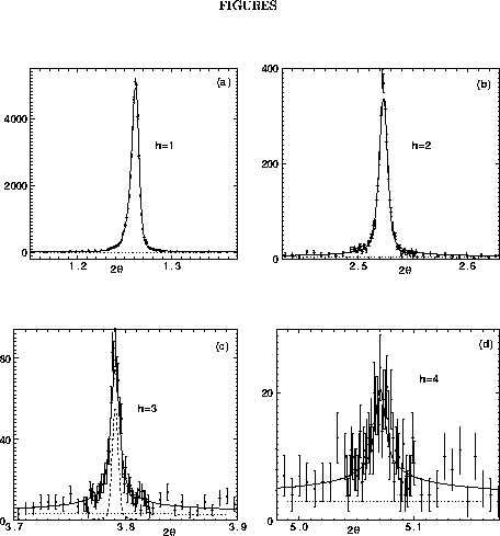
Figure 1 shows data for one sample in 40% PVP aqueous solution and the fits from the theory. By varying the concentration of PVP in the aqueous solution containing the multilamellar vesicles of DPPC, we have obtained D spacings that range from 67.2Å with pure water to 53.9Å with 50% PVP in a total of 21 samples.

Figure: Counts versus scattering angle ![]() (degrees) for the first four orders from a sample of DPPC with D=55.06Å.
The solid lines show simultaneous fits to all orders using Eq. 2
with reduced
(degrees) for the first four orders from a sample of DPPC with D=55.06Å.
The solid lines show simultaneous fits to all orders using Eq. 2
with reduced ![]() =1.8.
The dashed curve in (c) shows the longitudinal resolution. The horizontal
dotted lines show the background levels whose estimated uncertainties are
roughly 10%.
=1.8.
The dashed curve in (c) shows the longitudinal resolution. The horizontal
dotted lines show the background levels whose estimated uncertainties are
roughly 10%.
A detailed simultaneous fit to all the observed peaks of each sample,
such as illustrated in Fig. 1, yields the
fluctuation parameter ![]() for each sample;
for each sample; ![]() is plotted versus D in Fig. 2. Figure 2
shows a systematic decrease in the fluctuation parameter
is plotted versus D in Fig. 2. Figure 2
shows a systematic decrease in the fluctuation parameter ![]() with decreasing D (decreasing hydration). Since the higher order scattering
peaks become unobservable when
with decreasing D (decreasing hydration). Since the higher order scattering
peaks become unobservable when ![]() becomes large (somewhat in excess of unity, see Fig. 2
in Zhang et al. (1995b)) and since
becomes large (somewhat in excess of unity, see Fig. 2
in Zhang et al. (1995b)) and since ![]() grows with h according to Eq. 2, Fig. 2
gives one reason why there are fewer observable peaks for more hydrated
samples than for less hydrated samples.
grows with h according to Eq. 2, Fig. 2
gives one reason why there are fewer observable peaks for more hydrated
samples than for less hydrated samples.

Figure: Caillé fluctuation parameter ![]() for 21 samples versus the D spacing. Solid circles indicate highest resolution
(0.0001
for 21 samples versus the D spacing. Solid circles indicate highest resolution
(0.0001![]() ) data
and solid triangles indicate lower resolution (0.0003
) data
and solid triangles indicate lower resolution (0.0003![]() )
data taken on different synchrotron runs. All observed peaks were fit simultaneously.
)
data taken on different synchrotron runs. All observed peaks were fit simultaneously.
Other parameters in fitting the scattering peak shapes are the mean
domain size L and the dispersion ![]() in the distribution of domain sizes (Zhang et al., 1995b). Results for
these parameters versus D are shown in Fig. 3.
There is some trend toward greater domain sizes L with decreasing
D, but it is far less systematic than the dependence of
in the distribution of domain sizes (Zhang et al., 1995b). Results for
these parameters versus D are shown in Fig. 3.
There is some trend toward greater domain sizes L with decreasing
D, but it is far less systematic than the dependence of ![]() on D in Fig. 2. This can be understood as
due to extraneous factors in sample preparation, such as the extent of
annealing which affects the sizes of the multilamellar vesicles. Indeed,
L is not a fundamental parameter that reports interactions between
bilayers. The fact that the results in Fig. 2
are quite smooth compared to those in Fig. 3
is evidence that there is little correlation between the values of
on D in Fig. 2. This can be understood as
due to extraneous factors in sample preparation, such as the extent of
annealing which affects the sizes of the multilamellar vesicles. Indeed,
L is not a fundamental parameter that reports interactions between
bilayers. The fact that the results in Fig. 2
are quite smooth compared to those in Fig. 3
is evidence that there is little correlation between the values of ![]() and L and that the values of
and L and that the values of ![]() in Fig. 2 are not artifacts of sample preparation.
in Fig. 2 are not artifacts of sample preparation.

Figure 3: The mean length of scattering domains L (solid circles)
along the bilayer normal and the mean dispersion ![]() in L (open circles) versus D spacing.
in L (open circles) versus D spacing.
Our fits to the data and the values of ![]() allow the long tails of the peaks to be extrapolated and the total intensity
under the hth order peaks to be recovered. Then, using the standard formula
(Zhang et al, 1994),
allow the long tails of the peaks to be extrapolated and the total intensity
under the hth order peaks to be recovered. Then, using the standard formula
(Zhang et al, 1994),
the absolute values of the form factors ![]() were obtained. The phases
were obtained. The phases ![]() of these form factors are well known from other studies (McIntosh and Simon,
1986a) and will be confirmed later by our studies of electron density profiles.
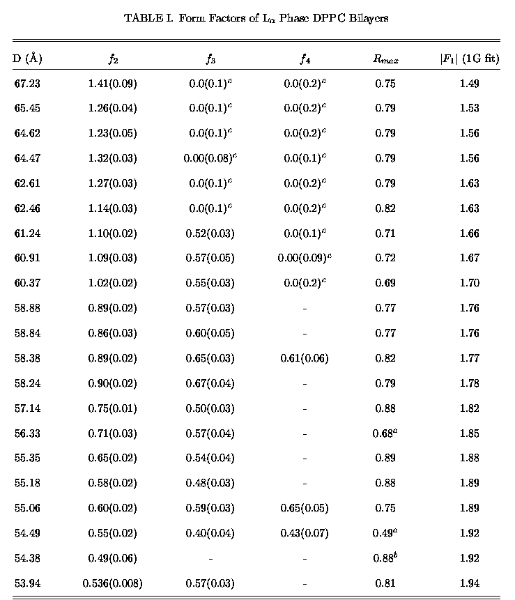
The form factor data are presented in Table I. There is no reliable way
to measure the relative magnitude of form factors with different concentrations
of PVP and different D spacings because they involve different samples.
When a large number of orders are measured, one can use the standard method
based on Parseval's theorem (Worthington 1969) to normalize the form factors
independently for each sample. We used this to obtain a first normalization,
but this is not accurate enough when so few orders are available and when
higher orders are suppressed by undulation fluctuations. Therefore, the
primary data are presented in Table I as ratios
of these form factors are well known from other studies (McIntosh and Simon,
1986a) and will be confirmed later by our studies of electron density profiles.
The form factor data are presented in Table I. There is no reliable way
to measure the relative magnitude of form factors with different concentrations
of PVP and different D spacings because they involve different samples.
When a large number of orders are measured, one can use the standard method
based on Parseval's theorem (Worthington 1969) to normalize the form factors
independently for each sample. We used this to obtain a first normalization,
but this is not accurate enough when so few orders are available and when
higher orders are suppressed by undulation fluctuations. Therefore, the
primary data are presented in Table I as ratios ![]() =
= ![]() /
/![]() of the higher order form factors
of the higher order form factors ![]() to the first order form factor
to the first order form factor ![]() for each of the 21 samples. Table I also shows the correction factor
for each of the 21 samples. Table I also shows the correction factor ![]() for the highest order observable peak for each sample. The correction factor
is the ratio of the uncorrected form factor to the corrected form factor.
The uncorrected form factor was obtained by simple integration of the background
subtracted peak to the end of the data range where the background became
comparable to the signal. In the final column in Table I are shown the
values of
for the highest order observable peak for each sample. The correction factor
is the ratio of the uncorrected form factor to the corrected form factor.
The uncorrected form factor was obtained by simple integration of the background
subtracted peak to the end of the data range where the background became
comparable to the signal. In the final column in Table I are shown the
values of ![]() obtained after fitting all the form factors to a model as will be discussed
below. To obtain our best estimate of the form factors
obtained after fitting all the form factors to a model as will be discussed
below. To obtain our best estimate of the form factors ![]() for h>1, multiply each
for h>1, multiply each ![]() by
by ![]() . However,
it should be emphasized that the basic data are only the ratios represented
by the
. However,
it should be emphasized that the basic data are only the ratios represented
by the ![]() , of
which there are 38 independent values in Table I.
, of
which there are 38 independent values in Table I.

Table i: Form Factors of ![]() Phase DPPC Bilayers
Phase DPPC Bilayers
Estimated errors are shown in parentheses, ![]() and
and ![]() .
.
For uncorrected ![]() ,
integration limits are
,
integration limits are ![]() ,
except:
,
except:
![]() :
: ![]() ,
and
,
and ![]() :
: ![]() .
.
![]() indicates
peak whose uncorrected intensity is below our detection limit.
indicates
peak whose uncorrected intensity is below our detection limit.